Category Archives: Build Tips

Resources for Science Olympiad competitions 2018-2019

We have released three kits now which are eligible for 2018/2019 Science Olympiad competitions, the Protege, intended for Elastic Launched Glider (Division B), the Carbonette 12 SO, intended for high ceiling Elastic Launched Glider contests, and the Senior Flyer, intended for Wright Stuff (Division C).

While these kits are one option for competition, you can also use the build videos for these models as a resource for building your own models for Science Olympiad or more broadly, indoor free flight contests in general.

Update: Protege kits purchased after 20 December 2018 no longer require special glues or sanding for the flaps. Use regular CA for the flaps, and do not sand them. These flaps are exceptionally durable and have greatly improved the building utility of this kit.

Protege build video:

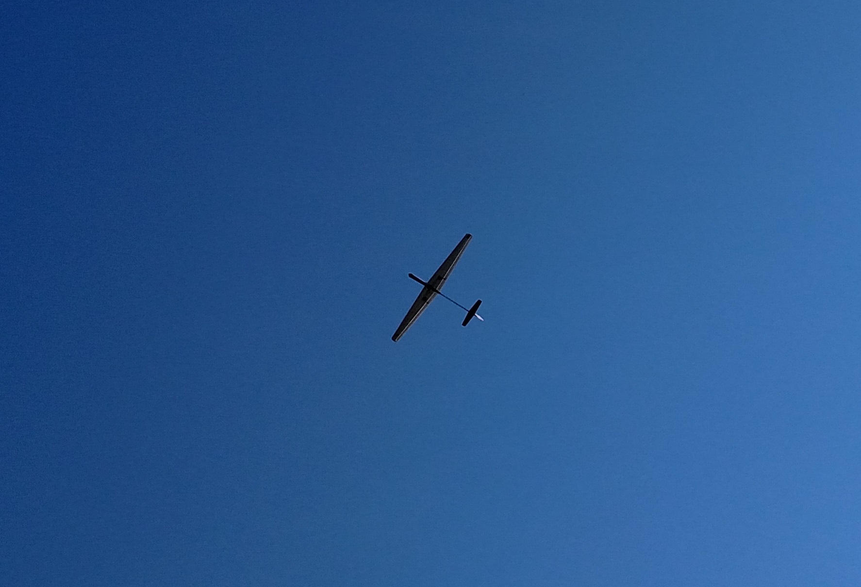
Protege flying session:

Trimming example:

If you purchased a Protege after 20 December 2019, it contains Vector Foam flaps which can be rigidly attached using CA glue. This enables you to split the flaps at the wingtips, allowing improved performance in some cases, and improve glide transitions in most cases.

Trimming notes on the Protege:

Low ceiling gliders can be very frustrating, but they are also very rewarding. You have to operate on the ragged edge to get that slow floating glide, and that makes the models extremely unforgiving.

Glide circle direction is being hotly debated in SO circles. Here’s my take on it. There’s no efficiency benefit to flying one direction or the other since the models are symmetrical. There is, however, an advantage to flying the model in a direction that’s optimized for human physiology. So if you’re right handed, it’s easier to launch in a right bank. That sets you up for a right turn if you’re flying lightweight gliders, but it requires a course reversal if you’re flying heavier ones, so they have to be flown in left glide circles.

Be sure to have students figure out how far back to pull to get within 1 foot of the ceiling. If they can transition between the girders, all the better. In terms of flight stability and CG, if you’re having trouble with flight trim, more stable is better.

When I’m trimming these models, I start with glide testing in a very conservative manner. I first ballast the models to get the CG at the flap join (this is for the Protégé and its variants) at the wing root and then keep adding up elevator until the model gives me a straight, steady glide. Then I start cranking in right rudder to force the right turn. The model will usually bank excessively when enough rudder is applied to get a 20-25’ glide circle, so I then grab the right wing near the root and twist in to give myself some left aileron (if looking down the pylon from straight in front, I should see the left wing level, and see a little of the underside of the right wing, meaning it is placed at a higher angle of attack). This will usually require inputting more right rudder.

Now proceed toward throwing the model harder, wings level, straight ahead. You want the model to fly straight briefly before nosing up a little and pulling off to the right in a shallow right bank. It should then gradually nose down into the glide, leveling its wings as the speed bleeds off. You’ll have to experiment with differing amounts of elevator, rudder, and right wing twist (remember that adding wing twist to the right wing gives you up elevator) until you get a satisfactory pattern.

The glide will likely deteriorate as you change these settings. If it starts stalling AFTER transitioning to glide (stalling before transition means you need either more right rudder or less up elevator), it’s ok to add nose weight, but if it starts diving a little, provided it does nose up on launch, you should probably just leave it alone until you’ve got the transition trimmed. If it’s banking steeply in the glide after transition, add more wing twist.

Now proceed to catapult launches at 60-70 degrees nose up in a right bank. Adjust the right bank until the model banks just enough to slide into the glide (basically what you showed in that video, but to the right). Unless the model pitches up a lot on launch, you can leave the elevator trim alone. If it starts to nose down on launch, add more up elevator. Observe the glide once your launches and transitions are ok and start adding/removing nose weight until the model is gliding as slowly as possible without stalling. After that you can start tweaking the glide circle for the best flight pattern by adjusting the rudder very carefully, with the understanding that this will change the amount of right bank you need on launch.

After that, just work on launch consistency. Funny tidbit: this procedure actually drives you toward the optimum CG even though you’re intentionally starting nose heavy.

Carbonette series build instructions:

Carbonette 12 flight trimming:

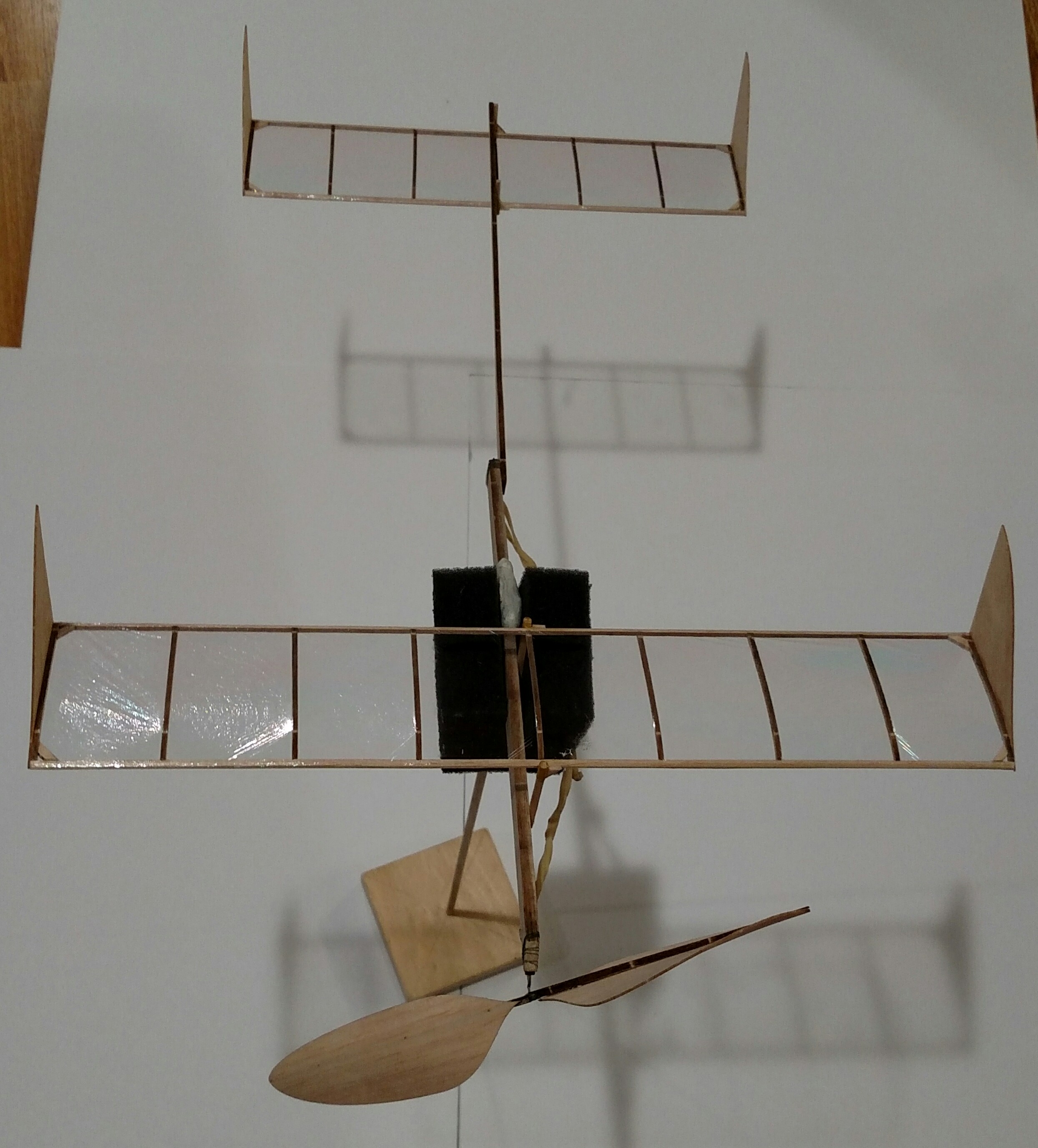
Senior Flyer build, part 1:

Senior Flyer build, part 2:

Senior Flyer build, part 3:

Senior Flyer build, part 4:

Senior Flyer build, part 5:

Senior Flyer build, part 6:

Removable tailboom mod:

Senior Flyer first flight:

Senior Flyer flight trimming:

How to build a torque meter:

https://www.youtube.com/watch?v=kDoMzyeIzWA

A note on optimizing flight trim with or without a torque meter:  Make up a motor, say 6″ long, get an accurate length on it, and then wind until it breaks, carefully counting the turns. Now divide braking turns by motor length to get breaking turns/inch. Start with the 14″ motor I recommend in the videos, and calculate max turns for that motor. Now you can wind easily to 85-90% of breaking turns on that motor. So, wind to that number, then back off to something you know won’t slam the model into the ceiling, and then reduce the backoff progressively until you’re just brushing the rafters. The next bit is, once you have the model trimmed for an efficient cruise by moving ballast around and adjusting the pitch trim (incidence changes, as mentioned in the video), to start playing with rubber motor length so that you can optimize the motor. What you want is for the backoff to roughly equal the number of turns at landing. And that process gets you 95% of the way to absolute max performance.

Spinster DLG – Free Plans!

J&H Aerospace is pleased to announce the successful completion of the new Spinster DLG, a super low-tech DLG that will cost about $30 to build and serves as an excellent introduction to DLG/F3K. It only takes a couple of evenings to build and has a removable wing so you can easily transport it to the flying field!

You will need the following materials to build this model:

  1. 1 sheet of Adams foam board
  2. 1 sheet of 3/32″x3″x36″ balsa, preferably C-grain
  3. 1 carbon fiber arrow shaft or Goodwinds.com boom, at least 32″ long (NOT a pultruded boom–those are too heavy).
  4. 4 micro servos; the Hextronic/Towerpro 9 g analog servos are more than sufficient. Search Ebay for “9g servo” to find the current lowest prices.
  5. 1 4+ channel micro receiver. Banggood has reliable dsm2 receivers for $6.
  6. 1 round cell Lipo battery (Turnigy 1000 mah is excellent).
  7. 1 Jst connector for the battery.
  8. Up to 3 servo extension wires (battery and aileron servos, depending upon length of wires–I only needed a battery extension).
  9. 1 small piece of 1/4″ balsa sheet.
  10. 1 piece of 1/64″ plywood (5″x5″ is sufficient).
  11. 1 piece of 1/32″ plywood (2″x2″ is sufficient).
  12. 1 piece of 1/16″ plywood (3″x10″ is sufficient).
  13. 1 .070″x.437″x23″ Carbon Rectangle strip from CST.
  14. 1 .016″x.118″ Carbon Rectangle strip from CST (at least 5″ long)
  15. 30 lb test spiderwire braided fishing line.
  16. 1 36″ length of .039 piano wire.
  17. 1 small block of blue foam or similar (at least 2″ cube).
  18. 1 sheet of computer paper.
  19. Masking tape, packing tape (or Blenderm), CA glue, and hot glue.

While it is possible to fly this model with a 4 channel radio, you will need to fly with a forward CG and use a y connector to slave the ailerons, which will eliminate the flapperon function. DLGs are very mode-sensitive (I use 1/8″ flapperon droop in glide and 45 degrees droop for landing). I recommend at minimum a Spektrum DX6i or equivalent (Flysky i6 may be sufficient with a micro receiver).

Plans are located here:

SpinsterDTFB_DLGparts

The building guide is located here:

Spinster Build Guide

Screen shots of the plans showing the parts layout:

Stay tuned for an upcoming build article at Flitetest.com and please bear in mind that the plans are still sparse on build notes. The article will clear that up, and we will share critical segments of it here. For those wanting a head start, you should begin by watching Nerdnic’s speed wing build video, which is very similar to the building methods used for this model.

F1D Propeller Construction

Now that Hope and Josh have recovered from the F1D World Championship, we are going to start uploading footage from various flying activities again. In the meantime, here are some propeller building videos we meant to upload back in February.

First up is how to double taper balsa spars. I use this technique for all of my propeller spars from ministick all the way up to unlimited:

Next up, how to build F1D propellers. This is a question we have received over and over, probably second only to how to cover indoor models. This is not the technique most indoor fliers use, and you may find that you do not like it. As they say, your mileage may vary.

We hope to begin uploading footage from Slanic very soon. Stay tuned as the updates begin. Josh’s phone has a couple hundred video clips from the past 6 months of flying and it all needs to be sorted out.

Boron gluing tool

A few people have asked me how I coat boron fibers with glue to secure them to motorsticks/tailbooms/etc. I made a coating tool some years ago that works great for this. It’s made from thin aluminum (about the same as a coke can). I formed it into a bowl shape with pliers, and over a hard surface, punched a sewing pin through it which was reamed out to about .020″ diameter. Using the sewing pin to punch through flares the hole slightly so that the boron fiber slides in more easily.

DSC05841

To use this tool, pour a glob of Duco in and thread your boron fiber through the hole. Wait about 10 seconds before grabbing the protruding end of the boron on the other side. You can now grasp the mostly dried end and pull the fiber all the way, being careful to pull straight down. This is best done while standing so that you can let the freshly coated fiber fall freely to a hanging position between your fingers. Wait for the glue to tack up and then set the fiber aside for use. The glue is reactivated using acetone once the fiber is in held in place on the intended component.DSC05842

Installing wire bearings and rear hooks

A recent discussion on the Yahoo Indoor_Construction forum revealed the need for more tutorials on installing wire bearings and hooks in rolled tube fuselages, particularly for beginning F1D fliers.

What follows is my personal method. Some will find it too heavy, others too difficult. This is the reason why there are many different methods for installing your hardware on an F1D. The model used below is actually an F1M. I use the same technique for both, but F1M’s are much easier to photograph.

Let’s get started…

I begin with a motor tube trimmed to length but without any taper cut into the front. My bearings are formed to allow proper clearance on the prop shaft, both for length and spacing from the motorstick. Usually my webbing material is the same thickness as the motorstick wood. In this case, the motorstick is .017 C grain and so is the webbing. The bearing and hook are .025″ wire because I had the weight budget for it and didn’t want any flexure in these parts. Notice the slight notch in the webbing sheet. This is created by sliding the sheet against the front of the motorstick and pressing it in slightly to crush the wood there. This does crush the top of the motorstick slightly as well, but that part will be cut off later anyway. Use the notch to get the exact width of the webbing.

DSC05822             DSC05823


Cut the webbing to length and size as shown using the notch as a guide.

DSC05825

I cut three pieces of webbing. One for the bearing, one for the hook, and one for facing on those webs.

DSC05826

Use a small amount of CA glue to secure the bearing and hook to the webbing. This is not a place to try to save a lot of weight. These parts will be under extreme loads at launch torque.

DSC05827

Cut the extra webbing piece in half to get your facing parts and use Duco to secure each half onto its respective piece of webbing. I actually hold the part in my fingers, crushing the facing slightly into the wire to get a firm mounting. The duco will set fairly quickly and result in a permanent entrapment of the wire.

DSC05829

Cut a slot in the bottom of the motorstick the length and width of the bearing so that it can be slid into place. Hopefully the only bow in your stick is along the seam, and the stick should bow toward the seam. You can then cut along the seam and make that part the bottom of the stick. The bracing wire’s tension will pull the stick straight. You will also need to cut a corresponding slot in the top of the stick if your bearing protrudes out the top as mine does to form the mounting eyelet for your bracing wire.

DSC05830

Smear a liberal coat of duco on the top and bottom of the webbing. Do not delay here…

DSC05831

Quickly slide the web/bearing assembly in place with one smooth motion. Do not stop until it is all the way in or it will stick quite permanently! I’m sure you could put a thin coat of Duco on and reactivate it with acetone, but this method has worked well for me for the past 4 years of contest flying and doesn’t add enough weight to be a problem, even on F1R models where weight is critical.

DSC05832

Now you can cut the from of the motorstick to a slope right back to the bearing wire (meaning you need to cut through the webbing, too). Use a sharp, new razor blade to do this without tearing the wood!

DSC05833

Cap the stick off with some more webbing. This cap is critical to keep the stick from collapsing under load in this area. It also prevents your fingers from crushing the stick while loading motors.

DSC05834

Once the glue is dried, trim the webbing with a sharp razor and your front end is finished.

DSC05839

Now on to the rear hook. Mark the motorstick for hook placement, including the dimensions of the facing.

DSC05835

Cut a slot in the motorstick using these guide lines and a sharp razor. The slot needs to be wider in the region of the facing.

DSC05836

Liberally coat the edges of the webbing with Duco just like you did with the bearing, and slide the assembly into the slot, pushing the eyelet of the hook straight through the other side of the motorstick so that the webbing is fully in place. I press a finger against the stick where the hook’s eyelet will punch through so that the wood only tears in the exact point where the eyelet protrudes.

DSC05837

Now seal the slot with a little more Duco, add your hook’s gusset, and the motorstick is ready for wing posts and bracing.

DSC05838